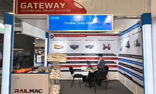
RailMac at InnoTrans 2026 Berlin Hall8.1‑245. One‑stop rail components, rolling‑stock solutions, diesel‑to‑electric retrofit, semi‑solid‑state battery & mining truck swap‑charge station. Connect for global rail business & custom projects.
SinoMac and RailMac: an integrated green-power value chain empowering the future of rail transit.
China-built, powering global rail transit. We look forward to welcoming you at Hall 8.1 · Booth 245.
Hailed as the "Olympics" of the global maritime industry, Marintec China 2025 took place from December 2 to 5, 2025, at the Shanghai New International Expo Centre. Centered on the theme “Innovation and Cooperation for Sustainable Maritime Development,” this edition showcased cutting-edge technologies, innovative achievements, and sustainable pathways across the global maritime sector. It attracted over 2,000 exhibiting companies and tens of thousands of professional visitors from more than 100 countries and regions, highlighting China's pivotal influence and open-cooperative stance within the global maritime industry.
As one of the most influential mining exhibitions in Central Asia, the Kazakhstan International Mining, Exploration and Coal Processing Exhibition (Mining Week) was grandly held in Karaganda, Kazakhstan from June 24 to 26, 2025. Focused on the entire mining process, this exhibition showcased a concentrated display of technological innovations, equipment upgrades and green solutions-catering to the industry’s full-chain demands and serving as a premier platform for global mining players to showcase technologies, exchange experience and explore partnerships.
Recently, the highly anticipated 2025 Vietnam International Maritime and Shipbuilding Exhibition concluded successfully at the Adora Convention Center in Ho Chi Minh City. As Vietnam’s largest and most specialized event in shipbuilding and maritime technology the exhibition gathered top shipbuilders, maritime service providers, and marine equipment manufacturers from around the world. SeaMac actively participated, comprehensively showcasing its innovative achievements and integrated capabilities in ship solutions and high-efficiency propulsion systems. The company engaged in extensive and in-depth exchanges with industry partners, achieving fruitful outcomes from its participation.
Against the backdrop of the booming development of the global shipping and maritime industry, Vietnam International Maritime Expo 2025 (Marine & Offshore Vietnam) will be held in Ho Chi Minh City, Vietnam from 19th to 21st November. As one of the most influential maritime events in Southeast Asia, this exhibition brings together top enterprises and innovations in the fields of global shipbuilding, offshore engineering, port equipment, new energy ship technology, etc., and provides an international platform for industry colleagues to exchange and co-operate and explore the market.
The International Exhibition of Engineering Machinery, Mining, and Concrete (Mining Indonesia) will be held in Jakarta, Indonesia, from September 17 to 20, 2025. As one of the most influential mining exhibitions in Southeast Asia, Mining Indonesia provides a professional platform for enterprises, experts, and practitioners in the global mining sector to showcase cutting-edge technologies, exchange industry insights, and explore collaborative opportunities.
The highly anticipated Middle East Saudi International Railway and National Road Transportation Exhibition (SAUDI RAIL) will be grandly opened in Riyadh, the capital of Saudi Arabia, from October 19 to 20, 2025. As an annual event in the field of rail transportation in the region, this exhibition focuses on Saudi Arabia's grand blueprint for rebuilding the future new city. With its strong industry influence and extensive market radiation, it has attracted many industry elites and enterprises to participate actively. The market heat continues to rise, showing a booming development trend.
From August 28 to 31, 2025, the highly anticipated biennial Russian International Railway and Rail Transit Exhibition (PRO/Motion Expo) will be held in St. Petersburg. The exhibition is the largest and most professional railway and transportation exhibition in Eastern Europe and Central Asia. PRO/Motion Expo brings together industry elites, corporate representatives and professional visitors from all over the world to witness the latest development achievements and cutting-edge trends in the railway and rail transit industry. Here, many internationally renowned companies will showcase their latest technologies, products and solutions, covering railway infrastructure construction, train manufacturing, communication and signal systems, intelligent transportation and other fields. From advanced train design and manufacturing technology to efficient railway operation and management solutions; from innovative rail material research and development to intelligent railway communication and control systems, various cutting-edge technologies and innovative achievements will be presented one by one, bringing a wonderful industry feast to the participants.
From September 22 to 25, 2026, the highly anticipated biennial Berlin International Railway and Rail Transit Exhibition (InnoTrans Berlin) opened grandly in Berlin, Germany. As the largest and most influential event in the global railway and rail transit field, InnoTrans Berlin brings together industry elites, corporate representatives and professional visitors from all over the world to witness the latest development achievements and cutting-edge trends in the railway and rail transit industry. The exhibition covers a number of key areas such as bridges and tunnels, public transportation, and comprehensively displays innovative technologies, advanced equipment and comprehensive solutions in the railway and rail transit industry. From infrastructure construction to operation management, from vehicle manufacturing to intelligent system applications, the exhibition content is rich and diverse, providing participants inside and outside the industry with an excellent platform for a comprehensive understanding of industry dynamics, exchanges and cooperation.